For the initial solenoid test, I used a breadboard and lots of alligator clips to join everything together. This is not ideal, as the junctions could have a relatively high resistance, plus it was a a pain to setup every time. I am aware that the rig will only be used a few times, so I didn't want to put much effort into making a dedicated electronics board for it. This all came to a head at the June Robots Go meeting, where I spent too much time talking and not paying enough attention to what I was doing and I wired the boost power supply in back to front AND swapped the + and - wires around! Luckily I quickly noticed the high input current on my adjustable power supply and turned it off. Amazing that the board still works. A robust design!
So last week I made up a ESP32 Dev board mount and added a firing switch and variable resistor, and wired the boost power supply board directly into the MOSFET pulse board. There is only one 6V input now and a supply goes off to the ESP32 Vin supply as well. It all makes a much neater wiring arrangement. Only the capacitor needs to be clipped onto the MOSFET board:
The solenoid housing for the first test (solenoid # 2), had nice mounting holes so I could mount it directly onto the MDF. For this solenoid I have to widen the MDF frame and laser cut and glue it up. A plastic housing was 3D designed and printed out:
Take not of the large gap between the solenoid plunger and the ball. The yellow spacers are 2mm thick and are made of EVA foam. I had a bit of a play testing out different gaps between the end of the solenoid plunger and the ball. With the ball resting on the MDF ball rest, the default gap is around 6mm. I then tested various different spaces to place the ball further away:
So, how did solenoid # 1 preform? Lets have some graphs to see how:
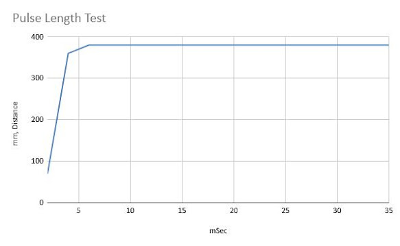
1) How does pulse length effect the distance travelled:
surprisingly once you get above 6 milliSeconds nothing changes. The coil does have quite a low resistance, so I presume the capacitor discharges much faster - up to 16A!
2) How does the plunger and ball distance effect the distance travelled?
The ball rest is around 6mm from the end of the plunger. There is a bit of a sweet spot of around 9-10mm, which means I use a 3mm MDF or two 2mm foam spacers. Interestingly, when I tried using my fingers to manually pick something in between, I managed to record a distance of up to 430mm!
3) Output Voltage Test:
Notes: Optimal firing would be 37.5V output with a 9mm spacing and a 10mSecond pulse. No tests where run with an input voltage of 12V feeding into the MOSFET board, as the robot we are using only has a 6-8.4V supply.


No comments:
Post a Comment